Tutorial: Paint a Screen
Requirements
Before attempting this tutorial, you must complete:
- Tutorial: Start AppMaster Builder in Enterprise Developer for Eclipse
- Tutorial: Create a User Area
- Tutorial: Create Projects
- Tutorial: Add Objects to the AMB Project
- Tutorial: Set Preferences and View Properties
- Tutorial: Learn Screen Painter Techniques
If you have closed Enterprise Developer, start it; then open the AppMaster Builder perspective.
To paint the BLDRCU (Parts Update) screen, we start the Screen Painter from the AppMaster Builder perspective, paint the text and entry fields, assign a field for system messages, paint a field to save the database key, and title the screen.
- Start the Screen Painter
-
- From the Project Explorer tab, expand c:\amb_tutorials\BLDRAPPL\dev1 > BLDRAPPL > BLDRUPD.
- Double-click the BLDRCU screen entry. This starts the Screen Painter.
- Show the grid
- To help you align screen fields, set the Screen Painter grid to show. If the grid is already showing, skip this step.
- In the Screen Painter, click Options > Show grid.
- Draw static text fields
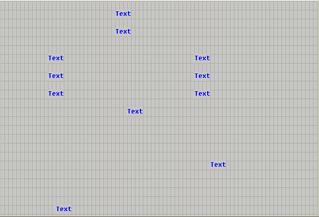
- Use the static text tool to drop static text fields onto the BLDRCU screen. Some of the static text fields serve as text labels
for entry fields. Others serve as screen title labels. Use the
Static Text Fields figure as your guide for this procedure.
Figure 1. Static Text Fields

- To toggle sticky mode on, click Tools > Sticky Mode. When sticky mode is toggled on, the tool you select next stays active until you toggle sticky mode off or select another tool.
- Click
Tools >
Static Text, or click the Static Text Tool icon on the toolbar
 . The mouse pointer changes to the static text tool.
- Using the Static Text Fields figure as your guide, position the tool on the top center area of the screen, where you want to paint the first screen title.
- Click to drop the field.
- Repeat steps 3 and 4 to drop the nine remaining static text fields. At this point, all fields read Text. Do not be concerned if the fields are not properly aligned.
- To toggle sticky mode off, click Tools > Sticky Mode.
- Increase static text field sizes
- Before you can assign descriptive text to these fields, you must first increase the size of each to accommodate the text.
Use the
Static Text Field Lengths table and the
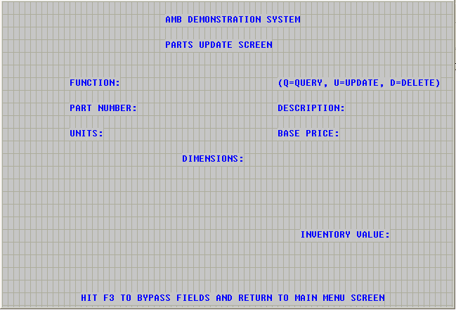
Labeled Static Text Fields figure as your guides for this procedure. While the table indicates the label for the fields, we will not actually put the
labels onto the fields until the next section.
Table 1. Static Text Field Lengths Static Text Field Label Length AMB DEMONSTRATION SYSTEM 25 PARTS UPDATE SCREEN 20 FUNCTION: 10 (Q=QUERY, U=UPDATE, D=DELETE) 30 PART NUMBER: 13 DESCRIPTION: 13 UNITS: 7 BASE PRICE: 12 DIMENSIONS: 12 INVENTORY VALUE: 17 HIT F3 TO BYPASS FIELDS AND RETURN TO MAIN MENU SCREEN 55 Figure 2. Labeled Static Text Fields
- First, activate the Tracking option. To do this, click Options > Show tracking. The bottom right field on the Screen Painter dialog box shows Track, indicating that tracking is active.
- On the BLDRCU screen, click the first screen title field, located at the top center. The anchor blocks appear. This field must accommodate the text AMB DEMONSTRATION SYSTEM, which is 24 characters in length.
- Move the mouse pointer to the right border of the field. The pointer changes to a double-sided arrow.
- Drag the border to the right until the LEN specification in the Screen Painter Tracking field reads LEN=24.
- Using the Static Text Field Lengths table and the Labeled Static Text Fields figure as your guides, repeat steps 2 through 4 for each text field.
- Label static text fields
- Next, label the fields with descriptive text. Use the
Labeled Static Text Fields figure as your guide for this procedure.
- Double-click the AMB Demonstration System field on the top center of the screen. The Text Attributes dialog box appears.
- Highlight the word Text in the Text field, located on the top right column of the Text Attributes dialog box.
- Type AMB DEMONSTRATION SYSTEM to replace it.
- Click the check mark
 to accept the change.
- Close the Text Attributes dialog box by clicking the x icon in the upper right corner.
- Using the Labeled Static Text Fields figure as your guide, repeat steps 1 through 5 for each static text field, substituting the appropriate label text in step 3.
- Draw entry fields
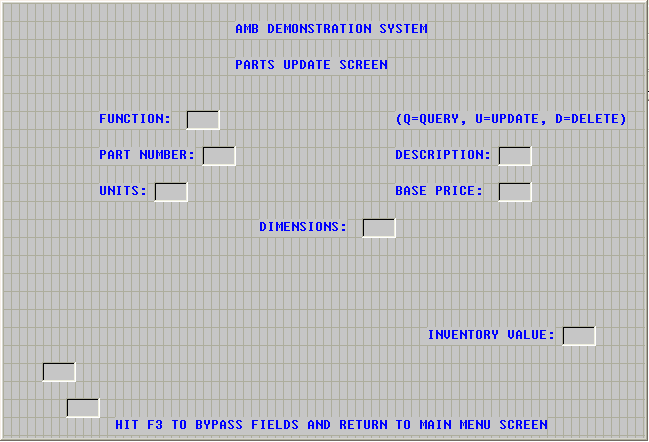
- Use the Entryfield tool to drop entry fields onto the BLDRCU screen. Use the
Entry Fields figure as your guide for this procedure.
Figure 3. Entry Fields

- To toggle sticky mode on, click Tools > Sticky Mode.
- Click
Tools > Entryfield, or click the Entryfield tool icon
 from the toolbar. The mouse pointer changes to the Entryfield tool.
- Position the tool to the right of the FUNCTION static text field.
- Click to drop the entry field.
- Using Figure 3 as your guide, position and drop the remaining entry fields. Do not be concerned if all fields are not aligned.
- To toggle sticky mode off, click Tools > Sticky Mode.
- Resize entry fields
- Because the Screen Painter default length for entry fields is 4, all of your entry fields are now four characters in length.
You need to make them the size needed for data entry. Use the
Entry Field Lengths table to determine field lengths.
Table 2. Entry Field Lengths Field Length Function 1 Part Number 8 Description 20 Units 2 Base Price 7 Dimensions 8 Inventory Value 12 Savekey (located below and to the left of the Dimensions field) 9 System Message (located below the Savekey field) 79 - Click the FUNCTION entry field. The anchor blocks appear.
- Move the mouse pointer to the right border of the field. The pointer changes to a double-sided arrow.
- Drag the border to the left until the LEN specification in the Screen Painter Tracking field reads LEN=1, and release the mouse.
- Repeat steps 1 through 3 for each entry field, dragging each border to the left or the right as necessary, using the Entry Field Lengths table to determine field lengths.
- Now is a good time to save your work. Click File > Save.
- Assign field attributes
- With the fields painted and labeled, we can now assign attributes to each field.
- Assign field attributes to DATA fields
-
- Double-click the entry field next to the FUNCTION text field. The Field Attributes dialog box appears.
- In the Name field, change DATA1 to function.
- Check Cursor. This positions the cursor in the Function field when you run the application.
- Click the check mark
 to accept the change.
- Close the Field Attributes dialog box.
- Repeat steps
1,
2,
4, and
5 once for each remaining entry field, using the following table to determine field names.
For the field with this label . . .
Change DATAx1 to . . .
FUNCTION:
function
PART NUMBER:
part-nbr
DESCRIPTION:
short-desc
UNITS:
units-instock
BASE PRICE:
base-price
DIMENSIONS:
dimensions
INVENTORY VALUE:
inv-value
1 x represents the number generated for the default name of the field.
- Assign attributes to the Savekey field
-
- Double-click the Savekey field.
- In the Name field, change DATAx to savekey.
- Check Protected. This prohibits the end user from entering data.
- From the Intensity drop-down list, click Dark. This changes the field from normal intensity to dark (hidden) so that the field does not display on the screen that the end user sees.
- Click the check mark
 to accept the changes.
- Close the Field Attributes dialog box.
- Assign attributes to the System Message field
-
- Double-click the System Message field.
- In the Name field, change DATAx to system.
- Check Protected. This prohibits the end user from entering data.
- Click the check mark
 to accept the changes.
- Close the Field Attributes dialog box.
- Assign Screen Parameters
- In this procedure, you assign screen parameters to the BLDRCU screen. First, we specify an internal screen title to appear
in all generated BLDRAPPL reports. Then, we assign a system message field to accept and display messages from the application.
And finally, we assign a CICS transaction ID to the screen. When you run the application, the transaction ID identifies the
screen to CICS.
- Assign an internal screen title
-
- Double-click on a blank portion of the screen. The Screen Parameters dialog box appears.
- In the Title field, type Parts Update.
- Assign the System Message field
-
- On the Screen Parameters dialog box tool bar, click EDITS. The Field Edit Messages and Attributes dialog box appears.
- From the Message Display Field drop-down list, select SYSTEM.
- Click OK. This returns you to the Screen Parameters dialog box.
- Assign a transaction ID for the screen
-
- On the Screen Parameters dialog box tool bar, click CICS. The CICS Generation Parameters dialog box appears.
- In the Transaction ID field, type BLDU.
- Click OK. This returns you to the Screen Parameters dialog box.
- Click OK. This returns you to the Screen Painter.
Note: The CICS transaction IDs for the BLDRCA and BLDRCM screens have been set for you.
- Align fields
- In this section, you use the alignment features of Screen Painter to clean up the appearance of the BLDRCU screen.
- Center the title fields
-
- Using one of the methods presented in the Select multiple fields section of the Learn Screen Painter Basics tutorial, select the AMB Demonstration System and Parts Update text fields.
- Click Arrange > Alignment. The Alignment dialog box appears.
- On the horizontal list, click Center.
- On the vertical list, click None.
- Click OK to make the alignment. The Screen Painter centers the screen title fields relative to the screen and each other.
- Align the Function and Units text fields with the Part Number text field
-
- Using one of the methods presented in the Select multiple fields section of the Learn Screen Painter Basics tutorial, select the Function, Part Number, and Units text fields.
- To set the Part Number field as the primary field, click on it. Its anchor blocks become solid.
- Click Arrange > Alignment. The Alignment dialog box appears.
- On the horizontal list, click Left.
- On the vertical list, click None.
- Click OK to make the alignment. AMB left aligns the Function and Units fields with the Part Number field.
- Align remaining fields
-
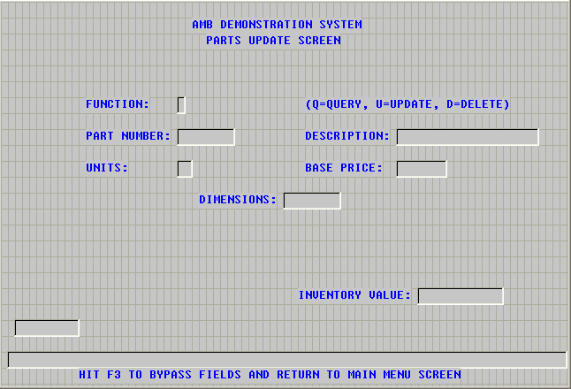
Figure 4. Completed Parts Update Screen

- Using the techniques you have learned in this tutorial and in Tutorial: Learn Basic Screen Painter Techniques, continue to adjust fields on the screen until they appear as shown in the Completed Parts Update Screen figure.
- Click File > Save to save your work.
- Click the x icon in the upper right corner to close the Screen Painter.
This completes the tutorial. Next, please complete Tutorial: Assign Screen Field Edits.